
Software development requires an efficient communication and understanding between all stakeholders involved in the project. One of the essential tools for effective communication and understanding is the sequence diagram. A sequence diagram is a graphical representation of the interactions between different components of a system over time. To create a sequence diagram that accurately depicts the interactions within a system, it is crucial to follow a well-defined process. They are commonly used in software development to depict the flow of messages between objects and the order in which those messages are sent and received.
In this article, we will explore how to create a sequence diagram using a use case-driven approach.
This article provides a step-by-step guide for creating sequence diagrams using a use case-driven approach. By following this process, you can create clear and comprehensive visualizations of the interactions within your system, helping to ensure that the system is designed to meet the needs of the users and that the interactions between components are well-defined and efficient.
The use case-driven approach focuses on identifying the key scenarios and interactions that a user will have with a system. This approach helps to ensure that the system is designed to meet the needs of the users and that the interactions between components are well-defined and efficient.
Step 1: Identify the use cases
The first step in creating a sequence diagram using a use case-driven approach is to identify the key use cases for the system. A use case is a description of a particular interaction between a user and the system. Some examples of use cases might include logging in, making a purchase, or updating a user profile.
Step 2: Create a use case diagram
Once you have identified the key use cases for the system, you can create a use case diagram to represent them visually. The use case diagram should show the different actors (i.e., users or external systems) that interact with the system, as well as the different use cases and their relationships.
Step 3: Develop the Use Case Description
For each use case in the use case diagram, develop a use case description with the flow of events section. The flow of events section should describe the steps that the user takes to interact with the system and the system’s responses to those steps.
Step 4: Develop Sequence Diagrams for Different Scenarios
Based on the flow of events in the use case description, develop the sequence diagrams for different scenarios: Normal, alternative and exceptions. The Normal scenario represents the typical path that a user takes to complete the use case. The Alternative scenarios represent any deviations from the Normal scenario that a user might take, and the Exception scenarios represent any errors or unexpected events that might occur during the use case.
The sequence diagram should show the interactions between the different objects over time, with each message represented as a vertical arrow. The order of the arrows represents the order in which the messages are sent and received.
The sequence diagram should also include any conditions or loops that are part of the interaction. For example, if a user enters an incorrect password when logging in, the system might display an error message and allow the user to try again.
Step 5: Refine and Revise
Once you have created the initial sequence diagram, you should review it carefully to ensure that all of the interactions are well-defined and efficient. You may need to revise the diagram or make changes to the system design based on your analysis.
The problem that the mobile banking application aims to solve is the inconvenience and time-consuming nature of traditional banking. With the mobile banking application, users can perform banking transactions and access their account information from anywhere, at any time, without having to physically visit a bank branch. Additionally, the mobile banking application provides users with a range of features and functionalities that are not available through traditional banking channels, such as depositing checks via mobile device, viewing special offers and promotions, and managing account alerts.
The aim of the mobile banking application is to provide users with a convenient and secure way to manage their finances on the go.
Step 1: Identify the use cases
here are some candidate use cases for a mobile banking application:
Step 2: Create a use case diagram
Step 3: Develop the Use Case Description
A use case description for the “Transfer Funds” use case in the mobile banking application:
Use Case Name: Transfer Funds
Actors: User
Summary: This use case allows the user to transfer funds between their own accounts or to other accounts.
Preconditions:
Basic Flow of Events:
Alternate Flows:
Postconditions:
Step 4: Develop Sequence Diagrams for Different Scenarios
Here are the sequence diagrams for the normal, alternate, and exception flows of the “Transfer Funds” use case in the mobile banking application:
Normal Flow Sequence Diagram:
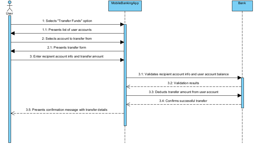 Normal Flow Sequence Diagram" width="853" height="486" />
Alternate Flow Sequence Diagram (6a):
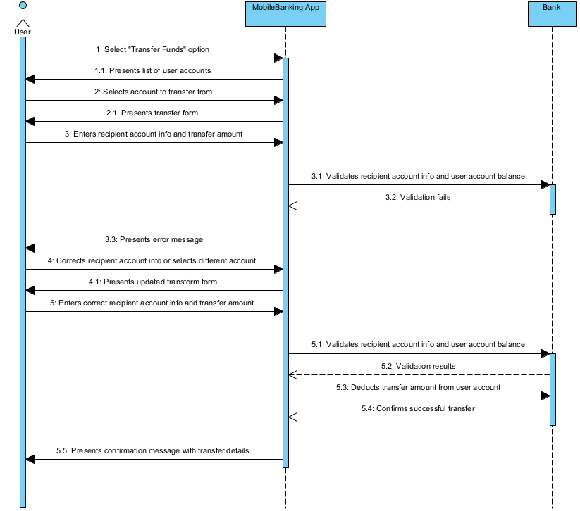
Alternate Flow Sequence Diagram (6b):

Step 5: Refine and Revise
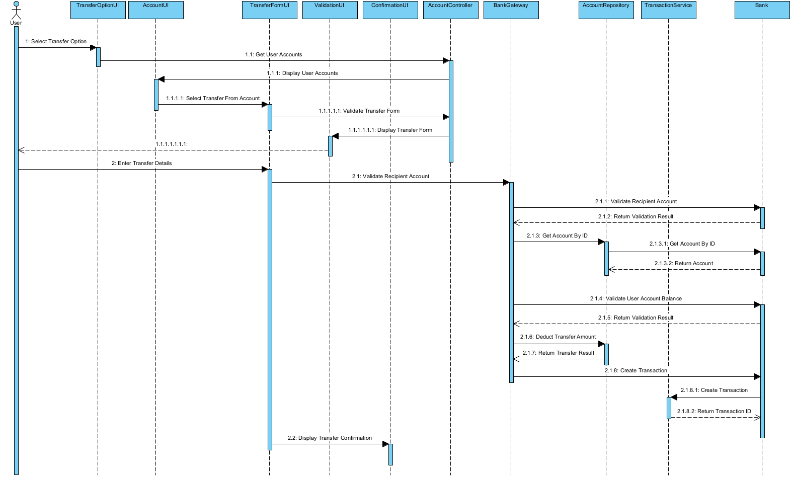
Now, lets elaborate only the normal flow sequence diagram into a more detailed MVC sequence diagram:
Using a use case-driven approach to create sequence diagrams helps ensure that the system is designed to meet the needs of the users and that the interactions between components are well-defined and efficient. Sequence diagrams are an essential tool in software design and development as they help to illustrate the interactions between objects or components within a system. A sequence diagram is a type of interaction diagram that depicts the flow of messages exchanged among objects or actors in a system. They are particularly useful in understanding and designing the behavior of a system in response to a specific use case. By developing a use case description with the flow of events section and then developing sequence diagrams for different scenarios, you can create a clear and comprehensive visualization of the system’s interactions.
Leave a CommentYou must be logged in to post a comment.